Wednesday 3 June 2015

Unfold Your Design Potential - Part 1


Software Looks Good.


In software demonstrations (demos), things look really nice, quick and seamless – demos are designed to be smooth, interesting and memorable. If you had the opportunity, you might have seen the SOLIDWORKS 2015 presentations, "Innovation Days", at a re-seller near you. As a CAD user, being able to see new features and understand the benefit, gives you the idea that you have better tools to help you and you’ll be able to do more work in less time…

The CAD software company invests a lot of money and time to prove these things to you, but often it’s not until you’re working with the software or in a training class that you find how effective it is. Coming from a Product Design background, I had a keen interest in how this tool would work, so I did my own research and this post is about that process.

 When I was working at Dassault Systemes, I presented some of this content to customers and reseller alike.
For the Flatten Surface Demo there was a complete shoe body shown. From that shoe, the result was the a surface that represented a part of the toe cap as below. 


The toe cap with spline on surface for intended split
 From the toe cap, another feature was inserted to define it even further. The Spline on Surface tool allows you to create a 3D spline which attaches itself to non linear surfaces and you're able use that same spline to trim away the unwanted elements. Pretty handy stuff.


The flattened toe cap

Finally from the trimmed portion, a new tool was used that has not been seen before. “Flatten Surface” was introduced. Magically, the organic shape was flattened. For me that was exciting enough (yes: CAD Geek) Then other elements were shown like how to improve the surface quality through the mesh style, the deformation of the product in different areas and ways to take it to manufacture. What good is a product if you can’t manufacture it?


Use a Real-World design


I'm part-way through a project and then realise I need to flatten the surface. Before this tool there would be a LOT of guesswork. In fact, I wouldn't even consider it. Generally for a one-off it's not worth it to have this functionality. So what do I do? It’s CRUNCH time! The boss is waiting on the design you’ve been tasked with and you don't have many options available.

I thought about that scenario and how I could demonstrate this new tool effectively in a so called "real-world" job. My trusty glasses case came to mind - they've been deteriorating for some time but held their shape and seem to have been made from a flat shape and formed into what they are. It's a thin flexible plastic case with a velvety finish on the inside to protect the glasses. There’s a button clip to close the case and it’s quite tough.

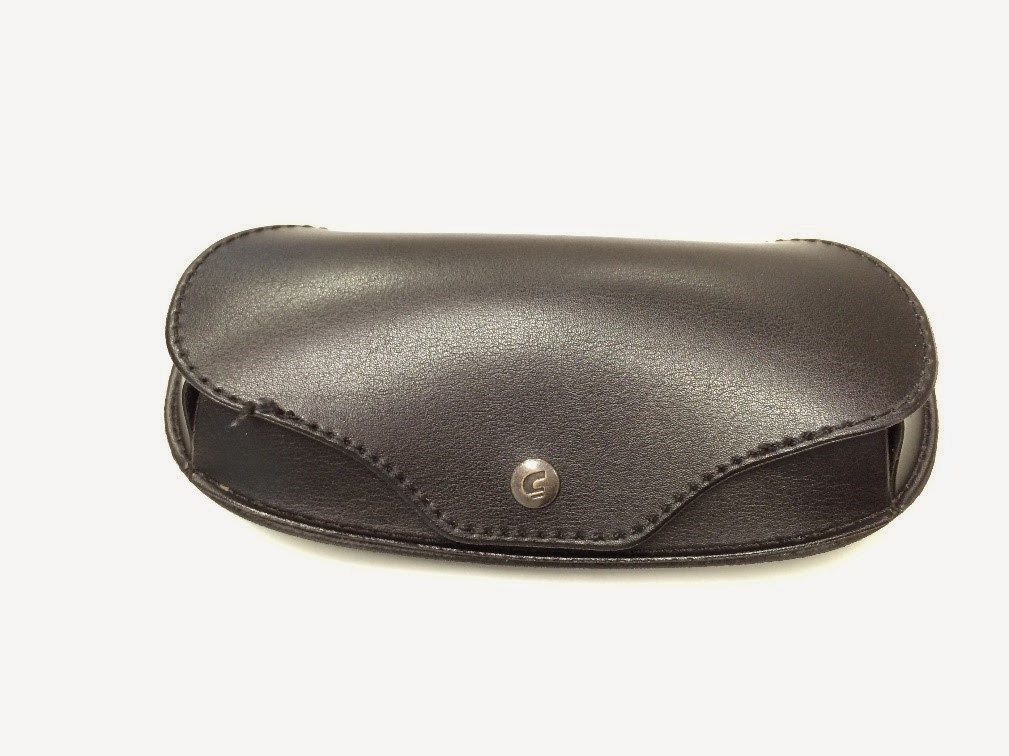
Trust Glasses Case - Front
In the images following you can see the case in the closed and open position. There is also a stress crack along the top of the case (below: red arrow) which developed over constant opening and closing: necessary to remove and replace the glasses as needed. Seeing this case and the crack in it, I wondered if when designed, the case was considered to be a throw away item and how long it would last. Firstly I wanted to understand how large the piece of material would have to be to create that shape and then I realised where the flatten surface function could be put to the test...


Glasses case rear showing the cracking surface


Glasses case in the open position

Analyse the Design


So how do we go about designing this case in the first place? There are many ways to create this part, or parts. Using SOLIDWORKS 2014 and earlier, the process would not differ greatly. I used several of the Product Design tools in this case: sweep, loft, and surfacing. And in SOLIDWORKS 2015 you won't find many differences to the approach and the techniques I used. I started out with basic overall shapes and trimmed them back - you can take a look at what I modelled here


The rough CAD model

I used surfaces mainly for the flexibility, then thickened the whole surface into a solid. It's a bit easier to work with solids in an assembly and drawing. You’ll notice the 3D model has only one part when it should actually be an assembly of 4 or 5 components, including: The outer cover which acts as a flexible hinge to open, the inside portion that supports the glasses, a lining to protect the glass from scratching, a “nose” support piece (not visible) and a button clip to hold the glasses in. The model is not completely accurate, but for the purpose of the exercise it’s all that’s needed.


Building Complex Shapes


If you have not used SOLIDWORKS to design complex or “organic” shapes then you can use the online help in the form of tutorials, the SOLIDWORKS online Help found under the option HELP and finally there is always new content on My.SolidWorks (I wrote a short post on that here). Whether it’s a SOLIDWORKS blog post, videos, forum posts, you'll most likely find it there.


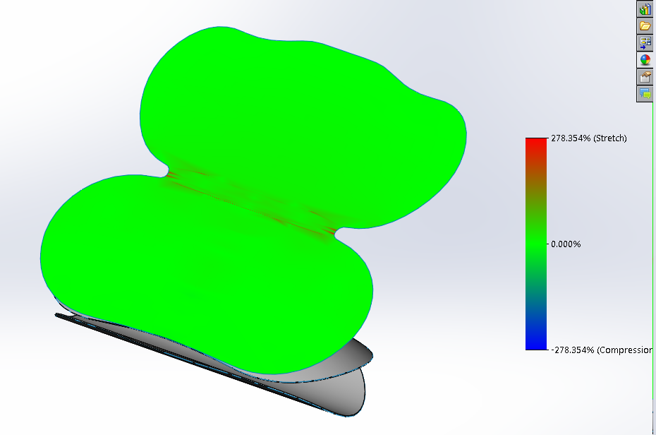
With a part, working out the area is fine – I can use the Evaluate tools to do that – Area, Mass, Centroid, Distance, Thickness analysis etc. are all easy to discover. I can select several surfaces to get an approximate area. Except when I want to get the part made, how can I determine how much material to use? Estimating the size of the material is always going to be tricky. In SOLIDWORKS Premium 2015 with the new Flatten Surface feature, I can select a surface and just click “Surface Flatten”.


The Surface Flatten tool is available from the Insert Menu> Surface> Flatten


This is the end of Part 1 - In Part 2 we'll see to how to unfold it...

No comments:

Post a Comment

Feel free to comment - you're ideas help me improve and design new content