A Fascinating Retro-Fit
When "nature called" at a
restaurant, what I found was design literally in the toilet*.
*In Australia toilet = restroom.
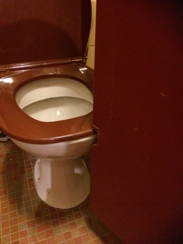
On entering the restroom - the first thing I noticed that the toilet was very
close to the door when I opened it.

A troublesome predicament
I thought, "There's
something wrong here!", but couldn't tell what it was at
first. The room was dimly lit, so it took me a couple of seconds to work out
what I was seeing, but the shots were pretty good from my mobile camera
and really makes it evident what I’m talking about.
I noticed something between where the toilet is, and the door: Primarily that the door looked really close. But then I looked at the edge of the door. Did you see it in the image above?
Is it Damage or "Design"?
Initially I thought the toilet door had some sort of damage. But no, it was
deliberately cut out. And cut with what looks like a hack saw. You can even see
how the first cut above was a little too high or so the tradie thought. You can imagine – the designer going “They’ll
notice that cut, I should make it a little lower” ha ha.

Damage or design?
Even more amazingly, with the toilet lid down, you can't open the door to
get access to the toilet. So that first retrofit cut on the door, the mistake was actually the right one. With that cut, the door could
at least fully-open with the toilet lid down. The “designer” didn’t double
check…
Why the Big Fuss?
To me it looked like the door was put
on after the cubicle was installed, which would be the sensible thing to do.
And it had to close inward due to the entry into the bathroom itself.
It led me to ponder...I guess design consideration was
only made for the clearance to the toilet after the install.
Once the door was mounted there was nothing else to
do but make a modification. And boy, is that modification a piece of work.
Why am I making such a big deal
out of this? Let’s ask these questions:
- How long did it take to cut out that
clearance recess?
- Were any other trades delayed (painter, tiler etc)?
It looks like the painting happened before the install as the recess was not painted. To me it seems that the owner missed this or may care too
much about what their customer's think. As a customer, seeing things like that, gives the impression of tardiness. What's going on tin the kitchen if this is how they look after the bathroom?
Herein lies the problem
Perhaps measurements weren't taken accurately for the toilet install, or
the room was retrofitted on the fly by trades’ people (or tradies). The main thing for me
was that modifications onsite were needed and delays were caused. The
result was a poor functioning door and the idea of a door for privacy was rendered
useless without the modification.
So what does an engineer do when faced with this issue? It can be catastrophic from
an engineering and manufacturing perspective, especially when we are dealing
with machinery or equipment that needs to be installed and commissioned in a
cost and time-effective manner.
The Right tools
Using the right tools designed
to work with manufacturing in mind is paramount. What are the right
tools?
When I went to technical college, we got a glimpse of CAD, but the tools were
mostly pencil/pens and tracing paper - believe it or not (for those that
were born in the late 80's and onward). We had exercises to create either
the relative 2D views or sketch out the 3D isometric based on partially
complete 2D technical drawings in our texts that were drawn
in 1st
angle or 3rd angle projection like in the image below:

Source: Engineering Drawing 3rd
Ed. A.W.Boundy
Those days were fun of course, you
really had to work your brain to work out projection lines, and show
hidden lines, break out views etc. but the amount of time it took was
long. At the time, you accept this as the most efficient/affordable tool. Of
course we want to get things done faster, easier and better; minimise or remove
errors.
2D Computer Aided Design (CAD)
So then 2D CAD came along. Now on a
computer screen we can delete lines, scale them, move and copy. I use both
2D a.k.a. CAD (describing two dimensional Computer Aided Design) and
3D Solid Modelling Design to get work done.
2D CAD can assist you in being able to accurately
represent at full-scale, the components and machines you are building. Depending on the complexity of the job,
or my clients', I might choose either, or a combination of a 2D and 3D CAD package.
Sometimes I am supplied DWG files (2D format); depending
on the job, I’ll be expected to use portions of or the whole file to create or
update a product. To edit, copy or modify the original drawing it is handy to
have more than a DWG viewer to read the drawing.
If I am using a 2D CAD package, then
being able to view and edit is great. But even more-so when I want to
create a 3D part - I can copy and
paste directly from the 2D CAD directly into the 3D package.
In this video by the team at SOLIDWORKS you
can see how to take a 2D DWG file, edit it, then bring it directly into a 3D
mechanical design system that shows how can utilise both 2D
and 3D tools in harmony.
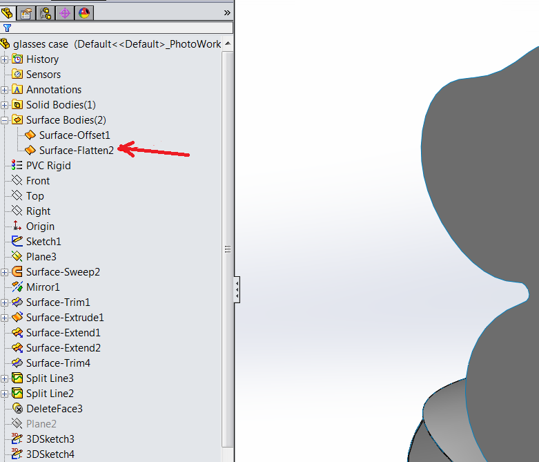
Where does 3D CAD come in?
So why is it important to be able to
visualise your models in 3D? In the image below you can see the finished
product (as mentioned in the video above).
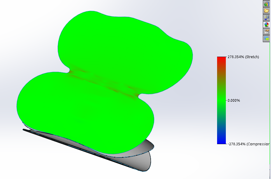
Not only can we visualise, but we can take several
components and assemble them like you would on the shop floor. There are videos
by SolidWorks on Youtube to see how it’s done.

Finally once assembled, you can test
whether the parts will interfere - you can tell right away whether parts will collide!
Here’s another video showing interference detection.
In the first example I made the assumption that a digital tool was not used,
but there are many factors that attribute to these types of errors: Sometimes
the drawings are not clear, the parts lists are incomplete or maybe the
specifications were wrong. Other times the drawing is clear but the floor plan
is incorrect or incorrectly measured up.
Closing Note
Having quality work reflects on you and your establishment, let alone the danger if we put this into an engineering perspective.
Those factors aside - I think this
article demonstrates that you're better with CAD, than without. And Computer
Aided Design is certainly not going down the toilet, far from it. We’ve heard
all about 3D printing and additive manufacturing, CAD on mobile, CAD in the
cloud. Technology is continuously improving and new ideas are being forged.
With CAD, we are able to visualise designs, test our parts and
assemblies and make informed decisions about the design process, but rushing
into anything will probably get you into trouble.
If you have a project or an idea and
you’re wondering how to get started or get it to the market, contact me.
Happy Designing!

A Fascinating Retro-Fit
On entering the restroom - the first thing I noticed that the toilet was very close to the door when I opened it.
A troublesome predicament
|
I thought, "There's something wrong here!", but couldn't tell what it was at first. The room was dimly lit, so it took me a couple of seconds to work out what I was seeing, but the shots were pretty good from my mobile camera and really makes it evident what I’m talking about.
I noticed something between where the toilet is, and the door: Primarily that the door looked really close. But then I looked at the edge of the door. Did you see it in the image above?
Initially I thought the toilet door had some sort of damage. But no, it was deliberately cut out. And cut with what looks like a hack saw. You can even see how the first cut above was a little too high or so the tradie thought. You can imagine – the designer going “They’ll notice that cut, I should make it a little lower” ha ha.

Damage or design?
|
Even more amazingly, with the toilet lid down, you can't open the door to get access to the toilet. So that first retrofit cut on the door, the mistake was actually the right one. With that cut, the door could at least fully-open with the toilet lid down. The “designer” didn’t double check…
- How long did it take to cut out that clearance recess?
- Were any other trades delayed (painter, tiler etc)?
Perhaps measurements weren't taken accurately for the toilet install, or the room was retrofitted on the fly by trades’ people (or tradies). The main thing for me was that modifications onsite were needed and delays were caused. The result was a poor functioning door and the idea of a door for privacy was rendered useless without the modification.
So what does an engineer do when faced with this issue? It can be catastrophic from an engineering and manufacturing perspective, especially when we are dealing with machinery or equipment that needs to be installed and commissioned in a cost and time-effective manner.
When I went to technical college, we got a glimpse of CAD, but the tools were mostly pencil/pens and tracing paper - believe it or not (for those that were born in the late 80's and onward). We had exercises to create either the relative 2D views or sketch out the 3D isometric based on partially complete 2D technical drawings in our texts that were drawn in 1st angle or 3rd angle projection like in the image below:
 |
Source: Engineering Drawing 3rd
Ed. A.W.Boundy
|


In the first example I made the assumption that a digital tool was not used, but there are many factors that attribute to these types of errors: Sometimes the drawings are not clear, the parts lists are incomplete or maybe the specifications were wrong. Other times the drawing is clear but the floor plan is incorrect or incorrectly measured up.
Closing Note
Those factors aside - I think this article demonstrates that you're better with CAD, than without. And Computer Aided Design is certainly not going down the toilet, far from it. We’ve heard all about 3D printing and additive manufacturing, CAD on mobile, CAD in the cloud. Technology is continuously improving and new ideas are being forged.
With CAD, we are able to visualise designs, test our parts and assemblies and make informed decisions about the design process, but rushing into anything will probably get you into trouble.
Happy Designing!