Friday, 24 July 2015

TeamWork for Everyone!


Thoughts
Team Work - When I think of teamwork I think ants. Teamwork forms the very basis of their existence. They always work together and adapt to a changing environment. Many design and engineering consultancies and businesses rely on teamwork and structured project management to succeed. For me it was surprising to also find dedicated teamwork messages in a children's animation. I was watching Monsters University with my daughter and I was pleasantly surprised that the story is based solely around team work and cooperation, where working as part of a team is better than working alone. I thought this show was a great teaching tool to help parents like me to prepare my child with these life lessons.
This post is about the messages conveyed in the Monster's University animation. I have no affiliation with Pixar or anything related to Monster's University.
Background
For a while I was pondering whether to write this post at all - I was just so surprised with the strong teamwork messages outlined in Monster's University in a clear and simple process. I had only completed a short Project Management Training course and discovered that team work and planning are integral to the success of any project. I'm no expert, but the simple messages I learnt in the training were right here in this kids' animation. Because the animation was amusing and visually vibrant it was already entertaining but the producers really worked on a story line that made it very engaging for me. It was one of those movies which I think should be part of a school curriculum!
Go to School Kids!
WARNING: Spoiler alert...It sounds a little weird, but in the "Monster World", power is generated by literally capturing a scream. Maybe not so much fun for kids, but bear with me...Monsters have all sorts of jobs, but there are a group of monsters who specialise in scaring kids. Monsters train hard to get the biggest screams and these guys (yes, a gender bias unfortunately) are the "Top Guns" of Monsters, the best of the best. To be the best of the best, you have to go to Monster's University (referred to as MU throughout the post). This University education has both the theoretical elements and practical tests. I guess this is the first lesson - school and study helps you improve.

Consequences
There are two main characters: the small, green, one-eyed monster, "Mike" and the big fur-ball "Sullivan" are at MU learning how to scare effectively. 
One-eyed Mike is diligent and studies hard, and believes with hard work and persistence you can achieve. Sullivan on the other hand, is more relaxed and relies on his size, looks (like a monster) and raw ability to scare. Mike is just a lovable guy and dedicated, but as he's told several times through the show, if you're not scary you won't make it. Sound like familiar typecasts? People still manage to do impossible things even when things "aren't possible", but that's another story.
Both of Mike and Sullivan try their hardest to do better than the other. They're so focused on proving they're better than the other that they forget outside factors. Through a showdown between the pair, they destroy equipment and are promptly expelled from University. Some actions can have serious consequences. If it's something risky, take time to think about what could happen. 
"There is no 'I' in Team"
Fortunately, this pair of monsters discovers a chance to get back into University by playing in the "Scare Games" - a set of team work tests to encourage cooperation and only teams can participate. Through necessity, Mike and Sullivan join Team "Oozma Kappa" (OK) in order to play in the games. However, Sullivan and Mike have not learnt to work together and compete against each other to win, neglecting their team mates.
Don't Ignore Rules
While the first task in the Scare Games is being explained, Mike and Sullivan are so focused on winning, that they miss some of the rules crucial to participating. The main rule was for the whole team to cross the finish line together. Although Mike and Sullivan finish in top placings, the rest of their team cross through separately in last place, not to mention some injuries. Team "OK" finish in last place and cannot move to the next round. When team members are not focused, mistakes can be made that affect everyone on the team.
Second Chance?
Sometimes we get a chance to try again. Through a fortunate coincidence, one of the other teams is disqualified and "OK" are moved up a place to continue in the competition. When you are in a team, things can still be tricky. Even though the team has been defined, roles outlined and tasks scheduled, not everyone is "paddling in the same direction" or with the same effort. There needs to be consensus with common objectives and an understanding of the requirements to get there.
Talk and Listen
Eventually Mike and Sullivan realise that they depend on the team to have a chance to win in the competition. In the following races, the team concentrates on the things that are important to run smoothly and end up doing very well - they focus on communication, cooperation, repetitive training, and effort by all team members. These activities help a group understand the objectives and function together.
You're All Welcome! 
In "OK" each of the team members is different: one has octopus arms, another has two heads, another is basically a furry bridge and of course there are the two main characters a giant monster with big teeth and claws and a green ball with an eye - Quite a diverse team! In one of their next tests, each of the team members is able to use their separate talents to win and move to the next round. People are different and can all contribute to a task.
Comment
I could go on with messages in this animation as there are so many: Like mistakes are inevitable and honesty beats cheating and deception for example. But I think if you are a parent or just discovering project management and team work in a workplace, then I encourage you to watch it for yourself (a good excuse to watch a kids flick). If you enjoyed this post and are interested, there are many others available in print and online like one I read recently by Bernard Marr.

Wednesday, 15 July 2015

A Community Champion


Cutaway of Trakka Motorhome by Michael Lord 


Surprise Guest!

It's always interesting to me to see other people's perspectives, and so with this post I've invited a guest blogger - a person for whom I have great respect. Michael Lord is a long term Engineer and Designer at the well-known and respected brand Trakka (manufacturer of Motorhomes and Caravans). He is also the Sydney SOLIDWORKS User group leader. 
Of course, coming from a SOLIDWORKS background myself, I wanted to know (and thought others might also like to know) about what Michael does, and how. It's interesting to note, that being a User Group leader is not a paid job.

Take it away Michael.....

How it Happened

When Alex asked me if I would like to guest blog for his site I was honoured. I first meet Alex Henry a couple years ago: He was at the time in his role as Territory Technical Manager - SOLIDWORKS at Dassault Systemes for Australia and New Zealand. And me, in one of my roles - this time as Coordinator of the Sydney SOLIDWORKS User Group.


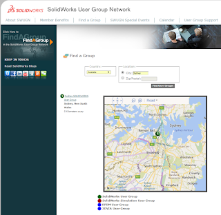
http://www.swugn.org/swugn/calendar/ugdetails.htm?id=173
 The Sydney User Group (SWUG) on the SOLIDWORKS User Group Network (SWUGN) webite

Cloak and Dagger...

My day time role is one of Design Engineer for Trakka, an Australian manufacturer of Motorhomes and Special Purpose Vehicles [Alex: at night he is a cloak and dagger Blogger J]. Over the many years we have changed dramatically how we design and developed our products: From the early years of physically building prototypes, modifying, rebuilding and producing templates (and the list goes on!). Next we incorporated 2D CAD but still with the need to produce multiple prototypes. 
Then, in 2005 we moved to 3D CAD - SOLIDWORKS - which changed everything!  Not just in the way we designed, but how we interacted with the likes of large global companies (Mercedes-Benz, Fiat, Volkswagen etc.), right through to how we manufactured.


One of Michael's Photo-real Images for Trakka


Guest Blogging Veteran

The guest spot on this blog was a similar request to five (5) years ago, when I was invited to write a post on using photoview 360. (I hadn't looked at it since I wrote it - It's nice to see my rendering has improved since then). That was the start of me becoming more involved in the SOLIDWORKS Community.


Michael's as Guest on Solidsmack's Blog

It sounds strange to think that there is a “Community” based around a Mechanical Design Software.   Yet there is!   My first interactions with this community came about seven years ago. First, whilst looking for help on the internet and with the discovery of many of the SOLIDWORKS Blogs, leading me to the start of Twitter - the new “social media” platform (at that time)! (You can still find me on Twitter at @ml13ml).  It was through social media that I now know many great people from around the world who are SOLIDWORKS users (as well as many other great people who use other CAD programs. But you can’t hold that against them J).

We have a Winner!

However, it was winning the SOLIDWORKS World 2011 Internet Correspondence Contest that got me noticed inside of SOLIDWORKS Corporation.

The SOLIDWORKS Blog Page


You can see my winning entry half way down in the comments section.   I hadn’t read that either since I wrote it all those years ago and I still crack myself up!

Michael's winning Comment for the Competition

Things kind of escalated from there.   Over the next couple of years I got a little more serious with my own blog: michaellord.me and decide that it was time that I should give a little more back to the SOLIDWORKS Community itself.  Which takes me back to the first paragraph in this blog and my role with the Sydney SOLIDWORKS User Group.


Michael's Blog page


A Community of Like-Minded Beings

The Sydney SOLIDWORKS User Group at the time had been dormant for a few years until I gave it a kick start, in July of 2012 (in a bloodless coup) [Alex: ha ha].    SOLIDWORKS User Groups are quite unique: They provide their members' access to a wide range of the SOLIDWORKS community both in regards to skill sets and also to a far greater diversity of industries.  As the meetings are normally in a relaxed atmosphere, the members are far more likely to share information relating to their technical skill, and also in regards to networking.

Also, as the user group is so diverse, there is greater variety of input and everyone has something to offer -  it doesn’t matter if you have had 12 months or 12 years of experience [Alex: I think even those with days of experience with SOLIDWORKS is relevant] - everyone uses the software in different ways.   With access to those "resources", there is the ability to learn additional skills and along the way, connect with a far greater range of people and companies that you’d otherwise may not have the chance to do so in normal working life.

A Modest Leader

   I try and avoid the term “Group Leader” because the role is really one of organisation.  My role within the Sydney SWUG is one very much that of a Coordinator.  Which sees me arrange to have people present content at the meetings, mainly on various elements of SOLIDWORKS or associated products.   However, it is not restricted to just the software; it may be hardware or a product, which I believe may benefit our members or how they do their job.   We always try to have two presentations at a meet, along with updating the group with news of what has been happening around SOILDWORKS (Beta release, SOLIDWORKS World and the like).


The Sydney SOLIDWORKS User Group (SSWUG) is very fortunate that we have the support of both this (NSW) States' SOLIDWORKS Resellers.  I can always call on either Intercad or Cadspace, who are always willing to provide one of their Application Engineers to give a Technical Presentation.   This, along with Dassault Systemes Australia or Asia Pacific South employees who have made themselves available to present in the past!   (It’s been a while since Alex presented!) [Alex: it’s true, it's been a while but my role has changed...]

Frequent Contact

We try to have at least four to five meetings per year.  These are held in a variety of locations around the Sydney suburbs to give as many people as possible the opportunity to attend.   I would like to be able to have more “site” visits/ meeting and have the group member present on how the SOLIDWORKS product is used in their business.   Personally I like to see other people’s factories especially in industries I have little knowledge of! The Sydney SOLIDWORKS User Group now has a database of over a 100 names and we see an average of around 30+ people attend the meeting.


SWUGN Website

If the Sydney SOLIDWORKS User Group sounds of interest to you then contact us - details of our next meeting are on the SWUGN website.   You can also connect via the Sydney SOLIDWORKS User Group on LinkedIn Group for regular updates.

The LinkedIn group for Sydney SWUG 

Part of Life

My involvement in the SOLIDWORKS Community is now just part of my daily life and personally I still feel that I gain more from my involvement with the SSWUG than I give!

With that, let me hand back Alex’s own Blog back to him ……. Thanks.

Thank you and Contact 

I am very grateful to Michael for sharing this post with us - thank you for giving us a little insight into your role at Trakka and for working so hard to keep the User group going.

As Michael mentioned, although he can get help from the resellers, this is about new products or how to use them.   Sometimes this content isn't enough and Michael will often stand up and share a presentation. And he's done a several for this group.   Seeing SOLIDWORKS used in a "real-world" environment is always exciting - I've seen several and recall a session on the basics of surfacing by Mike Puckett from SOLIDWORKS Certifcation team. In another session we saw how to built a full tug boat and the modelling techniques around modelling the hull of a sailing boat.  In my previous role, I made a presentation on how to use the "flatten surface" feature at the Melbourne user group in late 2014. I then created a subsequent 3-part post due to the interest it received.

 As there are so many tool sets in SOLIDWORKS to help with different tasks, users will find the ones that do their job the best way they know how - the way you use the software is likely to be different to someone else and will be interesting to others, prompting questions and also further developing your knowledge. Presenting at a user group is something that everyone can do and Michael I'm sure will welcome something you can show about the way YOU use SOLIDWORKS.

Also having a Site visit or a Company to host the User Group meeting, are a great ways to make the meetings even more interesting by understanding a bit about other industries. If you are able to provide a site visit, or want to contact Michael, you can do so through the user group, or the LinkedIn Group.
  
Hope to see you at the next SWUG meeting!

Tuesday, 7 July 2015

The Devil is in the Detail

A sketched concept of a shop display


You've heard the expression before, "the devil is in the detail". Why do we say that? Actually it was a different phrase before that according to Wikipedia, but in general the phrase means that the job being completed needs to be thorough. Depending n the scope of the project, in can be quite a tedious task to make sure that all the details needed are there. When it comes to engineering manufacturing and design, design and details are almost all that matter after you're through the concept phase. 

"How are we going to make that?"

The concept design is complete - the render is done and the customer is happy. The concept is passed on to the detail designer and they say to themselves "How are We going to Make that?". It's one of the challenges and also the benefits of design work - not just coming up with something that the customer likes, but then working out how everything will go together, what materials to use and what processes to use for manufacture. To define processes there needs to be documentation in written form, or outlined on the design information supplied to the manufacturer.

Render from a 3D  CAD model

The last point there is what I want to focus on - Times are changing, but mostly the detailing is shown on a 2D drawing.  This is the documentation that is sent off for quote and finally further details are added for manufacture. At one company I worked for, part of the process was doing a quote drawing by hand. We had a 2D CAD system but I guess it was the Design Manager's way of doing it quickly. 


The hand sketch was done on a typical border representative of the company's standard and the sketch tended to be pretty simple - it might be a rectangle with some holes of similar size drawn on it with dimensions so a fabricator could come back with a quote - just a overall sizes, material, "X" number of holes and quantity. Enough information that the manufacturer could come back with the pricing.

For some companies, the manufacturing drawing shows the supplier that you know what you're doing and what you want.


Weldment and steel detailing with welding notes


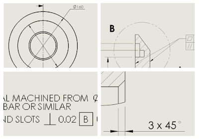
If the drawing looks professional, laid out correctly, all the details and finishes required - it shows your customers that you are professional.  I mentioned 2D earlier - 2D drawings and detailing used to be done by hand, then onto a CAD system where vector lines were used and today 3D in many flavours is being used in many organisations. BUT we still rely on those 2D drawings. 

3D CAD makes 2D easier

With 3D solid modelling there's no need to do some of the traditional things we used to do like project lines from view to view to get the picture of the top side and isometric "3D" view. 


3D Solid Model


There's minimal guess work. You're able to concentrate on the design and import dimensions or use smart functions to quickly get the detail you need for manufacture. The point is that advanced as our systems are you need to be able to put the right information into a drawing for manufacture. Eliminate duplicates, don't cross lines, space things evenly so that when your drawing is read, it's clear and concise and easy to follow.

Detailing on a 2D drawing sheet


The services HENRY design provides are from concept through to manufacturing drawings, but our "sweet spot" is in that design and detail phase. We take a design that is being developed, partially complete, or "almost there". We work together with you and add the detail as needed to create documentation and drawing packages ready for manufacture. If you'd like to discuss our range of services, please contact us through this link.


Friday, 19 June 2015

Is Design Going Down the Toilet?


A Fascinating Retro-Fit

 When "nature called" at a restaurant, what I found was design literally in the toilet*.

*In Australia toilet = restroom.

 On entering the restroom - the first thing I noticed that the toilet was very close to the door when I opened it.


A troublesome predicament

 I thought, "There's something wrong here!", but couldn't tell what it was at first. The room was dimly lit, so it took me a couple of seconds to work out what I was seeing, but the shots were pretty good from my mobile camera and really makes it evident what I’m talking about.

  I noticed something between where the toilet is, and the door:  Primarily that the door looked really close. But then I looked at the edge of the door. Did you see it in the image above?

Is it Damage or "Design"?

 Initially I thought the toilet door had some sort of damage. But no, it was deliberately cut out. And cut with what looks like a hack saw. You can even see how the first cut above was a little too high or so the tradie thought. You can imagine – the designer going “They’ll notice that cut, I should make it a little lower” ha ha.


Damage or design?

 Even more amazingly, with the toilet lid down, you can't open the door to get access to the toilet. So that first retrofit cut on the door, the mistake was actually the right one. With that cut, the door could at least fully-open with the toilet lid down. The “designer” didn’t double check…

Why the Big Fuss?

To me it looked like the door was put on after the cubicle was installed, which would be the sensible thing to do. And it had to close inward due to the entry into the bathroom itself.

  It led me to ponder...I guess design consideration was only made for the clearance to the toilet after the install. Once the door was mounted there was nothing else to do but make a modification. And boy, is that modification a piece of work.

 Why am I making such a big deal out of this? Let’s ask these questions: 

  • How long did it take to cut out that clearance recess? 
  • Were any other trades delayed (painter, tiler etc)? 
 It looks like the painting happened before the install as the recess was not painted. To me it seems that the owner missed this or may care too much about what their customer's think. As a customer, seeing things like that, gives the impression of tardiness. What's going on tin the kitchen if this is how they look after the bathroom?


Herein lies the problem

  Perhaps measurements weren't taken accurately for the toilet install, or the room was retrofitted on the fly by trades’ people (or tradies). The main thing for me was that modifications onsite were needed and delays were caused. The result was a poor functioning door and the idea of a door for privacy was rendered useless without the modification.

  So what does an engineer do when faced with this issue? It 
can be catastrophic from an engineering and manufacturing perspective, especially when we are dealing with machinery or equipment that needs to be installed and commissioned in a cost and time-effective manner.

The Right tools

  Using the right tools designed to work with manufacturing in mind is paramount. What are the right tools?

 When I went to technical college, we got a glimpse of CAD, but the tools were mostly pencil/pens and tracing paper - believe it or not (for those that were born in the late 80's and onward). We had exercises to create either the relative 2D views or sketch out the 3D isometric based on partially complete 2D technical drawings in our texts that were drawn in 1st angle or 3rd angle projection like in the image below:


Source: Engineering Drawing 3rd Ed. A.W.Boundy 


 Those days were fun of course, you really had to work your brain to work out projection lines, and show hidden lines, break out views etc. but the amount of time it took was long. At the time, you accept this as the most efficient/affordable tool. Of course we want to get things done faster, easier and better; minimise or remove errors.

2D Computer Aided Design (CAD)

 So then 2D CAD came along. Now on a computer screen we can delete lines, scale them, move and copy. I use both 2D a.k.a. CAD (describing two dimensional Computer Aided Design) and 3D Solid Modelling Design to get work done. 

2D CAD can assist you in being able to accurately represent at full-scale, the components and machines you are building. Depending on the complexity of the job, or my clients', I might choose either, or a combination of a 2D and 3D CAD package.

 Sometimes I am supplied DWG files (2D format); depending on the job, I’ll be expected to use portions of or the whole file to create or update a product. To edit, copy or modify the original drawing it is handy to have more than a DWG viewer to read the drawing.


 If I am using a 2D CAD package, then being able to view and edit is great. But even more-so when I want to create a 3D part - I can copy and paste directly from the 2D CAD directly into the 3D package.

 In this video by the team at SOLIDWORKS you can see how to take a 2D DWG file, edit it, then bring it directly into a 3D mechanical design system that shows how can utilise both 2D and 3D tools in harmony. 


Where does 3D CAD come in?

 So why is it important to be able to visualise your models in 3D? In the image below you can see the finished product (as mentioned in the video above). 

 Not only can we visualise, but we can take several components and assemble them like you would on the shop floor. There are videos by SolidWorks on Youtube to see how it’s done. 


 Finally once assembled, you can test whether the parts will interfere - you can tell right away whether parts will collide! Here’s another video showing interference detection.

 In the first example I made the assumption that a digital tool was not used, but there are many factors that attribute to these types of errors: Sometimes the drawings are not clear, the parts lists are incomplete or maybe the specifications were wrong. Other times the drawing is clear but the floor plan is incorrect or incorrectly measured up.

Closing Note

 Having quality work reflects on you and your establishment, let alone the danger if we put this into an engineering perspective.

 Those factors aside - I think this article demonstrates that you're better with CAD, than without. And Computer Aided Design is certainly not going down the toilet, far from it. We’ve heard all about 3D printing and additive manufacturing, CAD on mobile, CAD in the cloud. Technology is continuously improving and new ideas are being forged.

 With CAD, we are able to visualise designs, test our parts and assemblies and make informed decisions about the design process, but rushing into anything will probably get you into trouble.

 If you have a project or an idea and you’re wondering how to get started or get it to the market, contact me.

Happy Designing!

Saturday, 13 June 2015

Unfold Your Design Potential - Part 3

You may have seen Unfold Your Design Potential - Part 1 where I introduced the Fatten Surface feature and in Part 2, how it worked. In this final post, I take a look and see how we can use this information for manufacture. I also discuss a couple of questions and highlight enhancements to come.


Analyse for Manufacture


Once we have got an idea of the size of material needed, we start to think about quoting and manufacture.  It’s important to understand how much and where the material will stretch or compress when it is folded, or formed into the final shape. As we know when some materials deform, they have higher tendency to create stress concentrations in those areas, resulting in potential cracks that lead to material failure. You can see the results of cracks leading to material failure in the image below. 
Glasses case

My CAD model below in the deformation plot below isn’t perfect, but it seems to correlate with reality, showing me where the stressed areas are. Increasing the mesh quality, and some more control points will increase the accuracy of the deformation values, making them more realistic. I could also sped a bit more time modelling for accuracy.


The Deformation Plot


In the CAD model I made I did not spend enough time to get the flexible hinge of the cover perfect, but we can see the stretch/tension in the area of interest.


Prepare the Cutting Profile


Once the flattened shape is created, you end up with an extra single "Surface-Flatten<n>" in the feature tree.


Extra Surface Body in the Feature Tree

 Now you need some sort of 2D profile for quoting or for manufacture. How do we do that? We can make a 2D drawing from our 3D model and that is needed with many company design procedures. Some companies' processes determine the need to see a title block and a checking dimensions to ensure that the person on the other end has something to verify the DWG against. But if you need just the DWG, as with most tools in SOLIDWORKS, the feature is accessible from the Right mouse click or Context Menu> Export to DWG.


Preview of Export to DWG 

You get a clear preview of the shape and also have an option for orienting it prior to saving. This flattened shape can be sent off for nesting and cutting. We design processes don't stop there, but the feature has done it's job at this point. 

What if I Don't Have SOLIDWORKS Premium?


As the title suggests, you need SOLIDWORKS 2015 Premium and later to enable use of the Flatten Surface feature - Some questions follow: 

Q: Can the file be shared with another CAD user that does not have 'Premium? A:  Yes. For those who aren't using SOLIDWORKS Premium, the file shared with others will still contain the feature and the fattened surface, but the feature can't be edited in SOLIDWORKS Professional or Standard versions. However, the surface created can be viewed and manipulated as in a regular SOLIDWORKS part: Put into a drawing, save out as a dwg and saved out as a separate body. 

Q: Can the flatten feature have different amounts of stretch applied in different areas? A: At this time there is only mesh quality control.


The Final Piece - Determine if Fatigue is a Factor


We've covered several of the main points here - but I left one out. To use the tools that complete the full development cycle of a virtual lab environment, analysis on the glasses case for fatigue would be appropriate. We already saw from the previous posts that the glasses case was breaking and as I write this, the only thing holding the back and front together are the threads that have sewn them together - the formed material has now completely failed. But the sewing thread is still intact!!!


The case of the missing flexibility :-)

I would love to see how the repetitive load on the cover - the motion from opening and closing the case - would result in failure and how long I should expect it to last.

I would like to have used Fatigue Analysis but I don't have the software or projects to justify the outlay. If you have the software and would like to publish results or share with me, you've got the model here. The material might be PVC, but I can't be sure. However, it would be an interesting exercise...


Further Information


There are limitations as you'd expect for the first release of a new feature - it won't flatten if the surfaces are not joined or there's a hole in the middle. As I saw in in Michael Lord's blog, that limitation should be resolved in SOLIDWORKS 2016 - his photo journal from SOLIDWORKS World (SWW) 2015 - you'll find the reference about half-way down. :


Showing Flatten surface with holes in SW 2016 - M.Lord's photo from SOLIDWORKS World 2015

Normally what they show at SWW is only a hint of the enhancements that you get to see when the software  is officially released. I'm looking forward to new tools and the ways I can use them.

That's all for now. Catch you next time!